


Fedorov S.S., Sibir A.V., Gubinsky S.M., Gubinsky M.V., Gogotsi A.G.
April 11, 2019
One of the decisive advantages of the implementation of high-temperature chemistry processes (direct reduction of iron oxides, production of carbides, enrichment of carbonaceous materials, gasification and activation of coal, etc. -2].
By high-temperature processes we mean processes that occur in the temperature range of 1000 – 3000˚С. Such processes require a constant supply of thermal energy to compensate for heat losses and maintain the required temperature.
The source of thermal energy can be a hot gaseous coolant entering the furnace as a liquefying agent, combustion of fuel (solid or gaseous) directly in the bed, and electric heating. The use of the supply of hot combustion products to the bed and the combustion of fuel directly in the bed, as practice has shown, ensure the operation of furnaces at temperatures up to 900-1200 C [2-4].
In this regard, the main method of high-temperature treatment in a fluidized bed is the use of electric heating, which includes several areas: induction heating of electrically conductive particles of the fluidized bed, plasma heating, indirect heating by electric heaters and heating by passing current through the fluidized bed (electrothermal boiling).
The electrothermal fluidized bed ensures the operation of furnaces at bed temperatures in the range from 1000 to 3000C, while the duration of material processing is not limited and allows for a continuous production process.
The basic principle of the electrothermal fluidized bed organization involves the presence of three necessary components (Fig. 1)
- at least two electrodes;
- fluidized bed with conductive material;
- a current source.
The choice of the fluidized bed embodiment is determined by the level of process temperature, which determines the possibility of using refractory materials for the furnace working chamber. In this regard, all technological processes and furnace designs can be conditionally divided into:
- “low-temperature” – layer temperature 1000 – 1600?
- high-temperature – the layer temperature is 1600 – 3000 °C.

Fig. 1 Embodiments of the electrothermal fluidised bed [1]
1 – current source, 2 – housing with thermal insulation, 3 – fluidised bed, 4 – electrode,
5 – gas distribution grate-electrode, 6 – gas distribution grate,
7 – inert gas supply, 8 – removal of gases from the furnace, 9 – non-conductive lining of the furnace working chamber, 10 – conductive lining of the furnace working chamber.
In “low-temperature” furnaces, refractory materials can be used [5, 6], such as chamotte, corundum, magnesia, and dynamite. For “high-temperature” furnaces, graphite is used. This limitation determines the design of the furnace and the organisation of the technological process.
“Low-temperature furnaces with an electrothermal fluidised bed
Low-temperature processes in an electrothermal fluidised bed include direct reduction of iron using a solid carbon material as a reducing agent [7], production of titanium carbide TiC [8], silicon carbide SiC [9,10] and zirconium carbide [9], steam gasification of coke [12], heat treatment of metal products [13], production of zirconium chloride ZrCl4 [14], hydrogen production by hydrocarbon pyrolysis [15], encapsulation of quartz sand with pyrocarbon [16], and green oil calcination.
All designs of furnaces with a “low-temperature” electrothermal fluidised bed can be divided according to the direction of electric current flow in the fluidised bed: across the bed (in the horizontal plane) and the bed axis (in the vertical plane).
Figures 1a, 2 and 3 show the design of furnaces with two electrodes [17,18], which are immersed in a fluidised bed of conductive particles, which ensures heating of the bed as current flows from one electrode to the other in the horizontal plane. A similar furnace design is proposed by the author of the patent [19].

Fig. 2 Electrothermal fluidised bed furnaces for calcining petroleum coke [17].

Fig. 3 Electrothermal fluidised bed furnace for catalytic reactions [18].
1 – electrodes, 2 – fluidised bed, 3 – gas distribution grate, 4, 5, inert gas supply and evacuation, 6 – heat-insulating screens

Fig. 4 Furnace with an electrothermal fluidised bed [22].
1 – furnace lining, 2 – electrodes, 3 – fluidised bed, 4 – gas distribution grate
The second design variant with transverse electric current flow is a furnace with a cylindrical working chamber, the lining of which is an electrode. The second electrode is located in the centre of the working chamber. Thus, the current moves in a radial direction [7, 10, 12, 14, 20]. An example of such an iron oxide reduction furnace is shown in Figure 5 [7].

Fig. 5 Pects for direct reduction of iron oxides [7]
1- central electrode, 2- lined furnace body, 3- side electrode, 4- supply of inert gas, 5 – supply of reaction gas,
6- feeder for discharging cooled material
A number of furnace designs with an electrothermal fluidized bed with vertical current movement are also known [21-24]. As electrodes, the upper electrode is used, the lower part of which significantly overlaps the working space of the furnace and has a developed surface shape (crown). A gas distribution grid is used as the lower electrode (Fig. 6, 7)
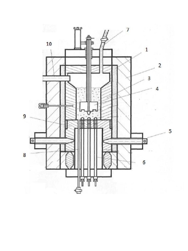
Fig. 6 Electrothermal fluidized bed furnaces for pyrolysis of hydrocarbons [21].
1 – thermal insulation, 2 – furnace body, 3 – working chamber made of refractory material, 4 – upper electrode, 5 – current supply, 6 – hydrocarbon supply, 7 – supply of carbonaceous material into the layer, 8 – discharge of carbonaceous material from the working chamber, – gas distribution grids – lower electrode, 10 – removal of gas from the working chamber.

Fig. 7 Bakes of an electrothermal fluidized bed for encapsulation of quartz sand with pyrocarbon [22]
1- Protective external heater, 2,3- moving upper electrode, 4- gas distribution grid – lower electrode, 5- supply of hydrocarbon gases.
The design of the furnace looks different with lattice electrodes located along the height of the boiling layer, between which there is a refractory nozzle [23] (Fig. 8). Thus, a limited electrothermal fluidized bed is realized. Electrodes are alternately connected to different phases.
The design of the furnace [25] (Fig. 9) implements a horseshoe-shaped current movement. Electrodes are separate elements of the gas distribution grid, separated by electrically insulating inserts in the form of partitions.
“High-temperature” furnaces with an electrothermal fluidized bed
“High-temperature” furnaces with an electrothermal fluidized bed have a similar design [7, 10, 12, 14, 20] with a central electrode and an electrically conductive working chamber, the lining of which is the second electrode. The working chamber is made of graphite materials, and inert gases argon and nitrogen are used as a liquid agent.
High-temperature furnaces operate in flow mode with constant loading of raw materials and unloading of processed material [25-28].
A typical design of a high-temperature furnace is presented in Figure 10.

Fig. 8 Pects with a compressed electrothermal layer [23].
1 housing, 2 gas distribution grids, 3,4 electrodes, 5,6 conductive rods, 7 electrical insulating sleeves.

Fig. 9 Bakes with an electrothermal fluidized bed [24]
1 – furnace lining, 2 – section of the gas distribution grid – electrode,
3 – vertical partition made of dielectric, 4 – current supply, 5 – boiling layer.

Fig. 10 High-temperature furnace for processing carbon material in a boiling electrothermal layer
1 – central graphite electrode; 2 – supply of raw material to the furnace,
3 – furnace body, 4 – thermal insulation, graphite lining of the working chamber, 6 – supply of inert gas, 7 – distribution chamber of finished material, 8 – gas distribution grid, 9 – removal of waste gases, 10 – refrigerator of finished material of the first stage, 2 – refrigerator finished material of the second degree.
When developing structures of furnaces with a boiling electrothermal layer, it is necessary to solve the issue of choosing constructive solutions of the following elements:
- furnace working chamber;
- electrodes;
- gas distribution grates;
- organization of removal of finished material;
- raw material loading;
- removal of waste gases;
- cooling of the finished product.
The second part of the article will be devoted to the analysis and recommendations regarding the selection of designs of the specified furnace elements.
Sources used:
1. Gupta, C. K., & Sathiyamoorthy, D. (1999). Fluid bed technology in materials processing. Boca Raton: CRC Press.
2. Zabrodsky S.S. High-temperature installations with a fluidised bed, M. Energia, 1971, 328 p.
3. Baskakov A.P. High-speed oxidation-free heating and heat treatment in a fluidised bed, Metallurgy, 1968, 223 p.
4. Thermal engineering calculations of alumina production furnaces / Gushchin S.N., Maisel S.G., Matyukhin V.I., Goltsev V.A., Ekaterinburg, UGTU, 2000, 229 p.
5. Volochko A.T., Shipko A.A., Demin N.I., Budzinskaya A.V. Monitoring the use of refractory materials at the enterprises of the Republic of Belarus / Casting and Metallurgy, No. 4, 2011, pp. 53-59.
6. Refractories for industrial units and furnaces: Reference edition, Book 1/ I.D. Kascheev et al.
7. Goldberger, William M., Zak Mark S. 2003, Process and apparatus for the direct reduction of irion oxides in an electrothermal fluidised bed and resultant product US Patent 2005/0092130 A1
8. James Tuot. Prodaction of TiC in an electrothermal fluidised bed Department of Chemical Engineering, McGi11 University, Montreal. Canada.August 1976, 680pp.
9. Goldberger William M. Method for the continuous production of carbides. U.S. Patent 4,543,240, 1985.
10. Borodulya, V. A. Method and installation for obtaining silicon carbide / V. A. Borodulya [et al.] Eurasian Patent No. 027539 of 31 August 2017.
11. Alekseeva T.I., Galevskiy G.V., Rudneva V.V., Galevskiy S.G.. Technological solutions in the production of zirconium carbide: analysis, assessment of the state and prospects // Scientific and Technical Bulletin of St. Petersburg State University. 2017. VOL. 23, NO. 1, PP. 256-270. DOI: 10.18721/ JEST.230126.
12. Knowlton, T.M., Pulsifer, A.H. and Wheelock, T.D., Coal char gasification in an electrofluidic reactor, Ind. Eng. Chem. Process Des. Dev. 8(4), 539, 1969.
13. Yukio Tanaka Electric direct heating method of metallic pieces US Patent 306034, 1962
14. Manieh A., Scott D. S. and Spink D. R. Electrothermal Fluidised Bed Chlorination of Zircon. The Canadian Journal of Chemical Engineering, Vol. 52, 1974, pp 507-514.
15. Kazhan, A.P.; Bogomolov, V.A.; Khovavko, A.I.; Bondarenko, B.I.; Simeiko, K.V. Study of the process of hydrogen production by hydrocarbon pyrolysis in an apparatus with an electrothermal fluidised bed. Energy Technologies and Resource Conservation, No. 2, 2012, pp. 27-31.
16. Bogomolov, V.A.; Kazhan, A.P.; Bondarenko, B.I.; Khovavko, A.I.; Simeiko, K.V. Encapsulation of quartz sand with pyrocarbon in an electrothermal fluidised bed Energotechnologies and resource saving, No. 5, 2013, pp. 33-36.
17. Aleksandr Kozlov, Yaroslav Chudnovsky, Mark Khinkis, Huajun Yuan, Mark Zak. Advanced Green Petroleum Coke Calcination in an Electrothermal Fluidised Bed Reactor, EPD Congress 204, 17 January 2014 Print ISBN: 9781118889763 |Online ISBN: 9781118889664 |DOI: 10.1002/9781118889664, pp1-8
18. F. Paul H. Johnson, Bartlesville, Okla. ELECTROTHERMIC FLUIDZED BED PROCESS US Patent 3499947, 1970.
19. Herbert S. Johnson, , Bartlesville, Okla.EECTROTHERMC FUDZED BED APPARATTUS US Patent 3006838, 1961.
20. Kervalishvili Z.Y., Olshonov M.Y., Pagava G.A., Sevryukov V.N., Sergeev A.L., Sukomskiy A.I., Kholin N.M. Reactor with an electrothermal fluidised bed SU 1003878, Published 15.03.83 Bulletin No. 10.
21. Bohomolov Valeriy Oleksiyovych, Bondarenko Boris Ivanovych, Kozhan Oleksiy Panteleimonovych, Semeyko Kostiantyn Vitaliyovych REACTOR FOR PYROLYSIS OF GAS-LIKE HYDROCARBONS UA 83147 Patent for utility model, Published 27.08.2013, Bulletin No. 16
22. Semeyko Konstantin Vitalievich, Bondarenko Boris Ivanovich, Kozhan Alexey Panteleimonovich, Dmitriev Valery Maksimovich REACTOR FOR HIGH TEMPERATURE PROCESSES IN THE SEVERALIZED LAYER UA 117157 Patent for utility model, Publ. 26.06.2017, Bulletin No. 12
23. Sevriukov V.N., Martiushyn I.G. Apparatus for direct heating of a fluidised bed SU 181211, Publ. 23.04.66, Bulletin No. 9
24. Nekhamin S.M. Method of electrothermal processing of dispersed material in a fluidised bed and device for its implementation RF 2663425 06.08.2018
25. Richard F. Markel, Greenville, S.C.; W. M. Goldberger,METHOD FOR HEAT TREATING CARBONACEOUS MATERIAL IN A FLUIDIZED BED US 4160813, Jul. 10, 1979
26. Mark S. Zak, William Mark Harrison, Joseph E. Doninger, METHOD AND APPARATUS FOR HEAT TREATMENT OF PARTICULATES IN AN ELECTROTHERMAL FLUIDIZED BED FURNACE AND RESULTANT PRODUCTS US 2005/0062205 A1, Mar. 24, 2005
27. Fedorov S.S., Gubinsky M.V., Foris S.M. Electrothermal fluidised bed furnace UA 108964, 10.08.2016, Bulletin No. 15.
28. Fedorov S.S., Gubinsky M.V., Foris S.M., Gogotsi O.G. Electrothermal fluidised bed furnace UA 107972, 24.06.2016, Bulletin No. 12.